
Embedded systems
Synchronizing Multiple Edge Devices Without a Central Clock
Edge devices often operate on independent oscillators, causing sensor data streams to drift apart. This article explores practical methods to align distributed timestamps using hardware features, software techniques, and protocol-aware strategies.
Why global synchronization fails on edge hardware
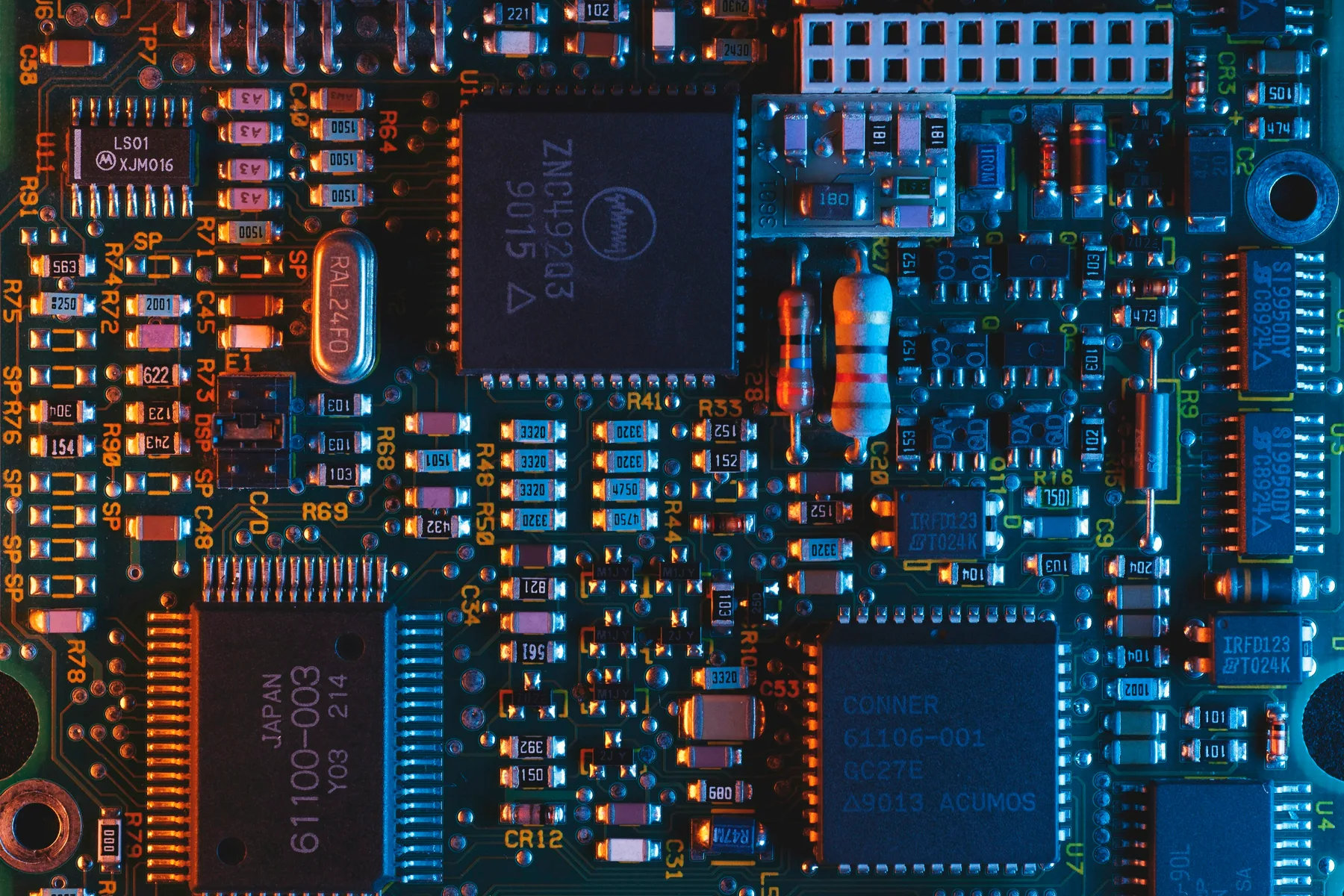
In many distributed sensor networks, each node contains its own oscillator—typically a quartz crystal or MEMS resonator—that generates the internal clock used to sample analog inputs and timestamp digital events. These oscillators are independent; there is no global timing reference shared across the network at power-up. Without a distributed synchronization mechanism, timestamps accumulate drift based on each device's nominal accuracy and environmental conditions. Over time, the timestamps assigned to events such as temperature readings, vibration samples, or motor commutations diverge, making it impossible to correlate data across nodes. This article examines why this drift occurs and presents methods to mitigate it without relying on a central time server.
Hardware limitations: crystal drift and jitter
Crystal oscillators exhibit two primary behaviors that degrade synchronization accuracy: drift and jitter. Drift is the gradual deviation of the oscillator frequency from its nominal value, often expressed in parts per million (ppm). A typical 32.768 kHz watch crystal may have a drift of ±20 ppm, which translates to a time error of about 1 second per day. Jitter, on the other hand, is short-term timing variation caused by temperature fluctuations, supply voltage noise, and aging. In safety-critical applications, even microsecond-scale jitter can cause false triggers or missed events. Moreover, most edge devices do not provide direct access to the raw counter value of the internal timer; instead, timestamps are generated by firmware at the moment of an interrupt or ADC conversion, adding software overhead that further obscures the true event time.
Software workarounds: timestamp interpolation and edge detection
When hardware timestamping is unavailable or insufficient, software techniques can partially recover synchronization. One approach is timestamp interpolation: if two devices sample a shared analog signal at slightly different times, the phase difference between their digital representations can be used to estimate the offset. By cross-correlating known patterns—such as a known waveform or a synchronization pulse—engineers can compute a relative offset and apply a correction factor to subsequent samples.
Another software method is edge detection on a broadcast signal. If a single GPIO pin is toggled simultaneously on all nodes (e.g., via a radio burst or a power-line signal), each device can record the instant its input pin changes state. The variance between these recorded instants reveals the inter-device clock offset. While this requires a dedicated synchronization line or wake-up signal, it does not require a global clock distribution network.
The role of hardware timestamping in CAN and SPI
Many embedded bus systems provide built-in timestamping capabilities. Controller Area Network (CAN) controllers often include a Time Stamp Counter that captures the CAN bit time at the moment a message is received or transmitted. This counter is typically driven by the CAN bus clock, which may be derived from a crystal on the bus transceiver. By reading the timestamp field in received frames, nodes can infer the relative timing of events on the bus. However, CAN timestamps are relative to the bus clock and are not inherently synchronized with the microcontroller's system clock unless both are derived from the same reference.
Serial Peripheral Interface (SPI) does not natively support timestamping, but the master can embed a timestamp in the data frame. The slave can then stamp the reception time using its own timer. The accuracy of this method depends on the synchronization of the SPI clock and the slave's ability to capture the timestamp within a single SPI cycle. In practice, SPI-based sync is best effort and suited for short-distance, low-jitter environments.
Comparing PTP, NTP, and local sync protocols
Precision Time Protocol (PTP, IEEE 1588) is the standard for sub-microsecond synchronization over networks. PTP operates by exchanging delay-request and follow-up messages between a master and slave, allowing the slave to adjust its clock offset and delay variance. While PTP can achieve high accuracy, it requires network stack support, often a dedicated hardware timestamping engine, and careful configuration of the network switches to minimize latency variation. For resource-constrained edge devices, the overhead of PTP may be prohibitive.
Network Time Protocol (NTP) is widely available but designed for synchronization over the public internet, where latency and jitter are orders of magnitude higher. NTP accuracy typically ranges from milliseconds to seconds, making it unsuitable for high-speed sensor fusion on a factory floor or drone swarm.
Local sync protocols, such as GPS disciplined oscillators (GPSDO) or hardware-based time-division multiplexing (TDM), offer a middle ground. A GPSDO provides a 1 PPS (pulse per second) signal and a disciplined 10 MHz reference that can be distributed to multiple edge nodes. Each node can then align its internal timer to the GPS reference, achieving microsecond-level synchronization without network traffic. However, GPS signals are unavailable indoors, and the hardware cost adds to the bill of materials.
A practical checklist for syncing distributed devices
When designing a distributed sensor network that requires timestamp alignment, consider the following steps:
- Characterize oscillator drift: Measure the ppm error of each device's crystal at operating temperature and document the expected drift rate.
- Evaluate available timing references: Determine whether GPS, a local rubidium reference, or a synchronized pulse line is feasible for the deployment environment.
- Select appropriate timestamping granularity: Decide whether sub-microsecond precision (PTP/GPSDO) or millisecond-order synchronization (interpolation/edge detection) meets the control or analysis requirements.
- Implement a fallback sync method: Design software that can operate without a global reference, using relative timestamps or drift compensation algorithms.
- Validate synchronization in situ: Use a oscilloscope or logic analyzer to compare timestamps on two nodes exchanging a known test signal, and adjust hardware or software compensations accordingly.
- Document assumptions and error budgets: Clearly state the expected timing error budget and the methods used to achieve it, especially for safety-critical or data-fusion applications.
***
*Disclaimer: This article is for educational purposes and does not replace a site-specific engineering assessment. For machinery, electrical, or safety-critical systems, consult the relevant standards and perform a site-specific risk analysis before deploying synchronization strategies.*
Explore Rootcastle engineering tools → · Public profiles and publications